EIGRP Load Balancing Lab (R1–R4) — Full Configuration Guide
This lab is based on a routing and load-balancing scenario provided by Network Bulls.
Solved and Answered by: Gurprabhjeet Singh
Formatting & Presentation done using: ChatGPT
In this lab, we will configure a 4-router EIGRP topology and implement path control and load balancing using route summarization.
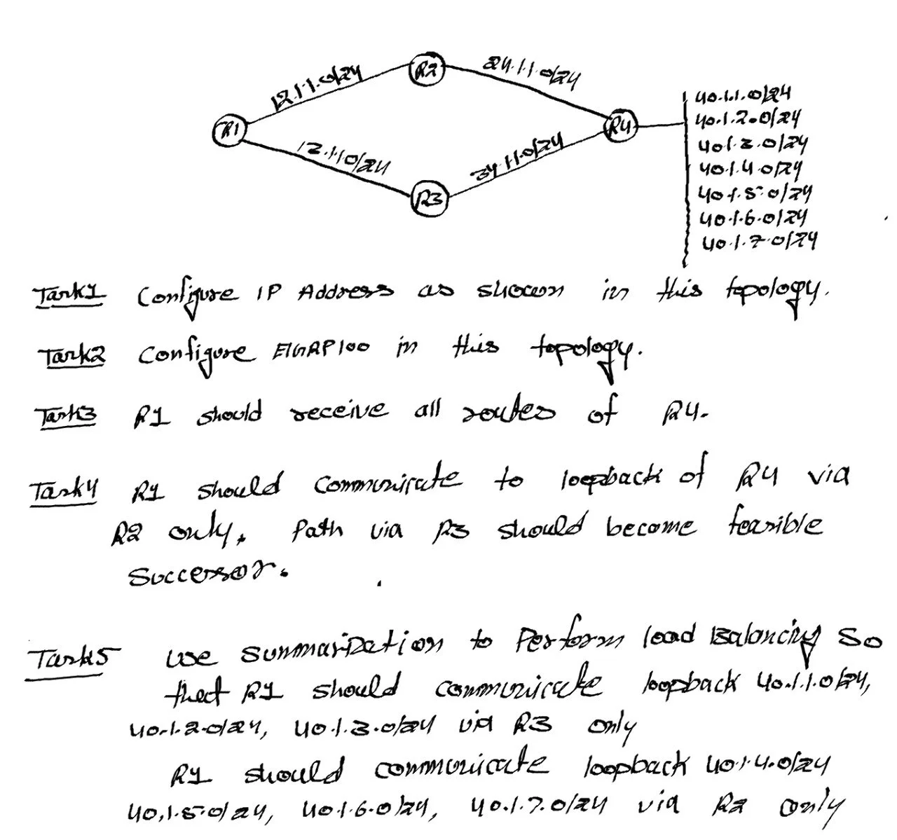
Lab Tasks (Objectives)
Task 1: Configure IP addressing as per the topology
Task 2: Configure EIGRP 100 in the topology
Task 3: R1 should receive all routes of R4
Task 4: R1 should communicate to R4 loopbacks via R2 only, and path via R3 should become feasible successor
Task 5: Use summarization to perform load balancing:
R1 should reach loopbacks 40.1.1.0/24, 40.1.2.0/24, 40.1.3.0/24 via R3 only
R1 should reach loopbacks 40.1.4.0/24, 40.1.5.0/24, 40.1.6.0/24, 40.1.7.0/24 via R2 only
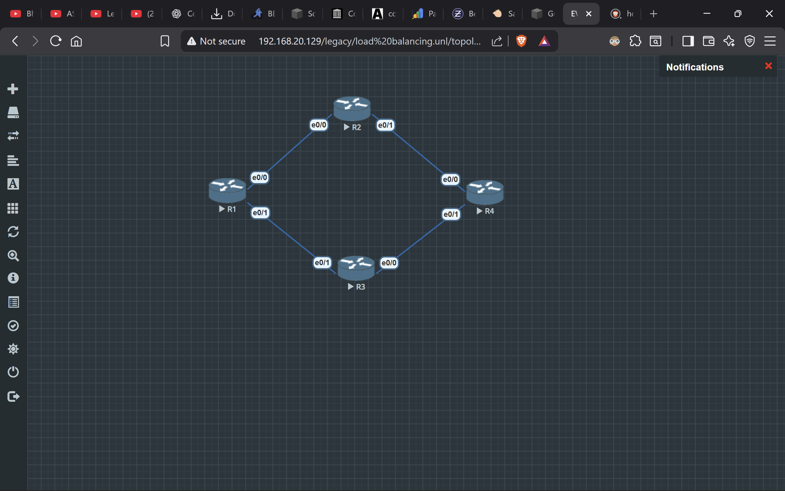
Topology Interface Mapping
The routers are connected in a diamond shape:
R1 e0/0 ↔ R2 e0/0
R1 e0/1 ↔ R3 e0/1
R2 e0/1 ↔ R4 e0/0
R3 e0/0 ↔ R4 e0/1
IP Addressing Plan (Task 1)
Link Networks
R1–R2 Link (12.1.1.0/24)
R1 = 12.1.1.1
R2 = 12.1.1.2
R1–R3 Link (12.1.0.0/24)
R1 = 12.1.0.1
R3 = 12.1.0.2
R2–R4 Link (24.1.0.0/24)
R2 = 24.1.0.1
R4 = 24.1.0.2
R3–R4 Link (34.1.0.0/24)
R3 = 34.1.0.1
R4 = 34.1.0.2
R4 Loopback Networks
R4 has these loopback networks:
40.1.1.0/24
40.1.2.0/24
40.1.3.0/24
40.1.4.0/24
40.1.5.0/24
40.1.6.0/24
40.1.7.0/24
Task 1 + Task 2: Configure R1 (IP + EIGRP)
en
conf t
hostname R1
no ip domain-lookup

interface e0/0
 ip address 12.1.1.1 255.255.255.0
 no shutdown

interface e0/1
 ip address 12.1.0.1 255.255.255.0
 no shutdown

router eigrp 100
 no auto-summary
 network 12.1.1.0 0.0.0.255
 network 12.1.0.0 0.0.0.255
end
wr
Task 1 + Task 2: Configure R2 (IP + EIGRP)
en
conf t
hostname R2
no ip domain-lookup

interface e0/0
 ip address 12.1.1.2 255.255.255.0
 no shutdown

interface e0/1
 ip address 24.1.0.1 255.255.255.0
 no shutdown

router eigrp 100
 no auto-summary
 network 12.1.1.0 0.0.0.255
 network 24.1.0.0 0.0.0.255
end
wr
Task 1 + Task 2: Configure R3 (IP + EIGRP)
en
conf t
hostname R3
no ip domain-lookup

interface e0/1
 ip address 12.1.0.2 255.255.255.0
 no shutdown

interface e0/0
 ip address 34.1.0.1 255.255.255.0
 no shutdown

router eigrp 100
 no auto-summary
 network 12.1.0.0 0.0.0.255
 network 34.1.0.0 0.0.0.255
end
wr
Task 1 + Task 2 + Task 3: Configure R4 (IP + Loopbacks + EIGRP)
en
conf t
hostname R4
no ip domain-lookup

interface e0/0
 ip address 24.1.0.2 255.255.255.0
 no shutdown

interface e0/1
 ip address 34.1.0.2 255.255.255.0
 no shutdown

interface loopback1
 ip address 40.1.1.1 255.255.255.0

interface loopback2
 ip address 40.1.2.1 255.255.255.0

interface loopback3
 ip address 40.1.3.1 255.255.255.0

interface loopback4
 ip address 40.1.4.1 255.255.255.0

interface loopback5
 ip address 40.1.5.1 255.255.255.0

interface loopback6
 ip address 40.1.6.1 255.255.255.0

interface loopback7
 ip address 40.1.7.1 255.255.255.0

router eigrp 100
 no auto-summary
 network 24.1.0.0 0.0.0.255
 network 34.1.0.0 0.0.0.255
 network 40.1.0.0 0.0.255.255
end
wr
At this stage, R1 will learn the loopback networks of R4 using EIGRP.
Task 4: Force R1 to Prefer R2 (R3 as Feasible Successor)
To ensure traffic from R1 to R4 goes via R2 as the best path, we increase delay on the R1 → R3 link.
Run this on R1:
conf t
interface e0/1
 delay 2000
end
wr
This makes the R2 path the successor route, and the path via R3 becomes the backup route (feasible successor if conditions match).
Task 5: Load Balancing Using EIGRP Summarization
Now we will use summarization so that certain loopbacks are preferred via R2 and others via R3.
Summary Requirement
Traffic flow should be:
Via R3 only:
40.1.1.0/24
40.1.2.0/24
40.1.3.0/24
Via R2 only:
40.1.4.0/24
40.1.5.0/24
40.1.6.0/24
40.1.7.0/24
Configure Summary on R2 (towards R1)
Networks 40.1.4.0/24 to 40.1.7.0/24 can be summarized as:
40.1.4.0/22 (mask 255.255.252.0)
Apply this on R2 interface facing R1 (e0/0):
conf t
interface e0/0
 ip summary-address eigrp 100 40.1.4.0 255.255.252.0
end
wr
Configure Summary on R3 (towards R1)
Networks 40.1.1.0/24 to 40.1.3.0/24 can be summarized as:
40.1.0.0/22 (mask 255.255.252.0)
Apply this on R3 interface facing R1 (e0/1):
conf t
interface e0/1
 ip summary-address eigrp 100 40.1.0.0 255.255.252.0
end
wr
Now R1 will reach:
40.1.1.0/24 to 40.1.3.0/24 via R3
40.1.4.0/24 to 40.1.7.0/24 via R2
Verification Commands (Run on R1)
Check EIGRP neighbor adjacency:
show ip eigrp neighbors
Check learned EIGRP routes:
show ip route eigrp
Check successor/feasible successor:
show ip eigrp topology
Traceroute testing:
traceroute 40.1.2.1
traceroute 40.1.7.1
Expected result:
40.1.2.1 should go via R3
40.1.7.1 should go via R2
Conclusion
In this lab we configured IP addressing, loopbacks, and EIGRP 100 across four routers.
We controlled path selection by tuning delay, and we achieved load balancing using EIGRP summarization so that specific loopback ranges are reached through specific routers.
Credits
Question Provided By: Network Bulls
Solved & Answered By: Gurprabhjeet Singh
Formatting & Presentation done using: ChatGPT
Topology given by Network Bulls
Topology made by Gurprabhjeet Singh